Close

Page 22 of 45 FirstFirst ... 12202122232432 ... LastLast
Results 211 to 220 of 449
  1. #211
    UPDATE: new coolant reservoir location: http://jeeplab.com/showthread.php?13...ull=1#post3638


    The second independent/separable step is getting rid of the stock coolant reservoir (it's in the way of the charge air pipe for stage 2 as well), and installing a new reservoir in a different location.

    Here's the new reservoir:


    It's a Meziere 28oz Coolant Recovery Tank: https://www.meziere.com/ps-1444-1377-wr100s.aspx


    And this is where it gets mounted, behind the front bumper on the passenger side:


    This requires drilling holes and tapping threads. Take your time and double check the positioning, mark where you want the holes, etc. I actually mounted mine slightly differently than Prodigy's instructions. Their instructions show the tank mounted slightly further back and lower, causing the bottom of the tank to hang down lower than the part of the frame that it is mounted to. I found that there was barely enough room to mount mine flush with the bottom of the frame. The positioning of the top mounting hole ended up being VERY close to a large existing hole in the frame, so i had very little room for error when drilling that hole.

    Don't repeat my mistake when tapping the threads: I used the drill motor with the thread tap, spun it too fast, and got it stuck in the hole, then ended up snapping the tip off in the hole. That was fun to drill that out. Lesson learned: tap VERY SLOWLY. You're supposed to twist the tap by hand, but I just couldn't keep it steady enough with my hand. I ended up using the drill motor again, but this time I oiled the tap for lubrication, and did my best to simulate twisting by hand with the drill motor by doing short, slow, smooth bursts of drilling, to avoid overheating the tap.

    The original hose from the radiator to the coolant reservoir gets reused. Just run it straight down from the radiator cap and find a path forward to connect up with the new reservoir.


    Yes, you will have to remove the two mounting bolts and pull the reservoir out a bit if you want to take the cap off and check the coolant level in it. I would much prefer another semi-transparent plastic container that is easy to visually check, like the one in the RIPP kit. But the space where RIPP places their reservoir just isn't available with the turbo installed.

    Also, this reservoir is much smaller than the stock reservoir. I spent some time looking up info about how much 50/50 coolant/water mix expands/contracts with temperature. I don't remember specifics, but I did find enough info to conclude that this reservoir is pretty much the smallest you could possibly go for the amount of coolant in the Pentastar. Because it's so close, it might just take a little trial and error to get it filled to the correct level so that it doesn't overflow when hot to the extreme (idling in traffic on a hot summer day), and doesn't allow air to be sucked into the system when cold on the coldest winter days.
    Last edited by UselessPickles; 11-23-2014 at 06:42 PM.

  2. #212
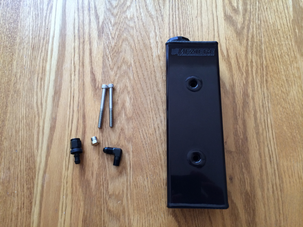
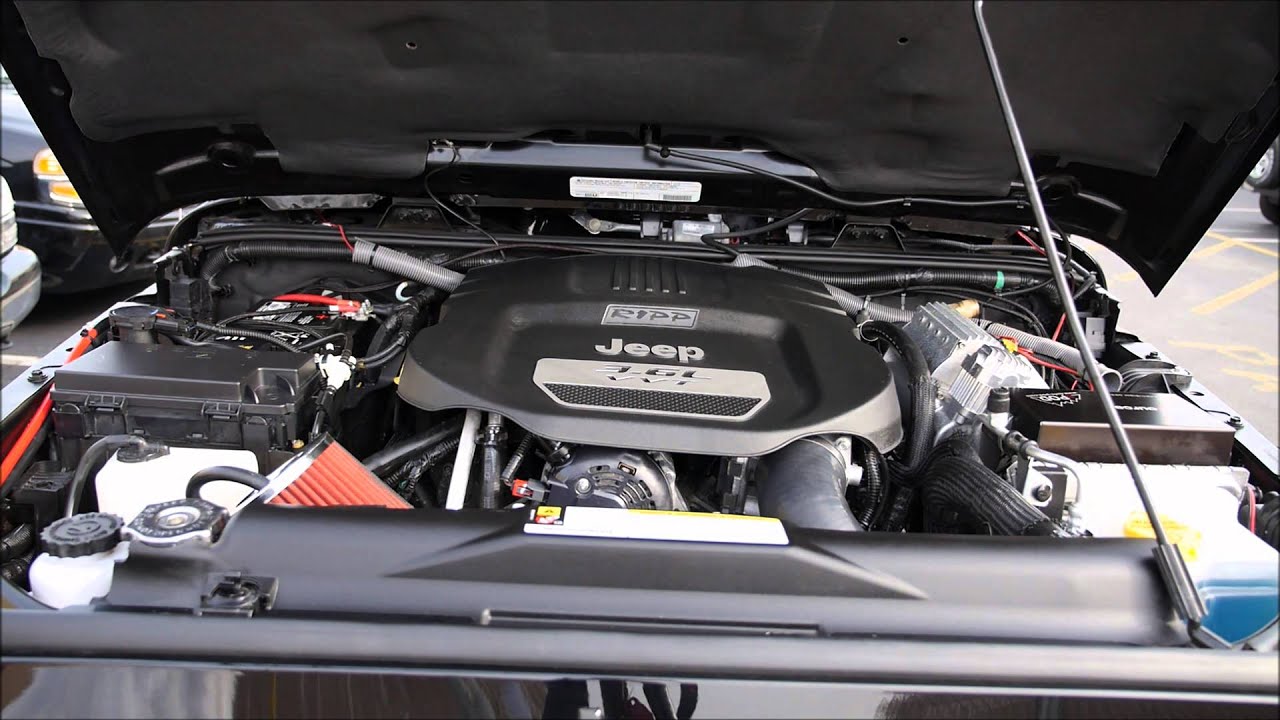
    Let's take another look at this coolant reservoir:


    The vent for the reservoir is just directly on top of the reservoir, at bumper level. Not only is this pretty low for a vent on a Jeep that may go in deep water, but it's quite exposed to rain water that runs down behind the bumper. The filtered cap will keep debris out, but water runs right through it (I tested!). I found this to be unacceptable, but easy to fix.


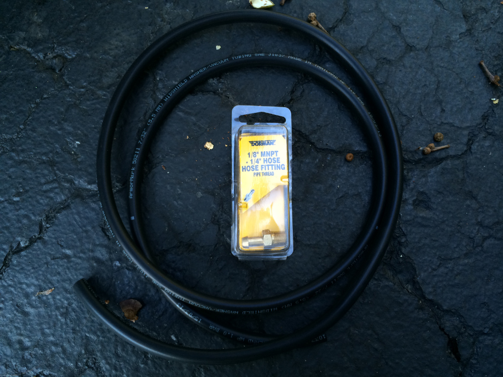
    That's about 4 or 5 feet of 7/32" vacuum hose and a 1/8" male NPT to 1/4" hose adapter, from a local auto parts store. Just replace the filter cap on the reservoir with the hose fitting.


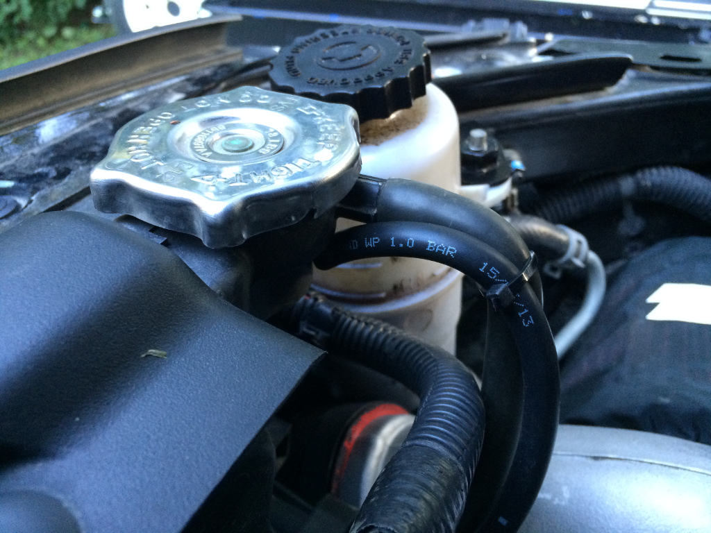
    And run the vent hose along the same path as the coolant overflow hose:


    No more worries about getting dirty water into the coolant system.


    Follow this link to skip to the next post with installation details: http://jeeplab.com/showthread.php?13...ull=1#post3589


    -------- UPDATE --------

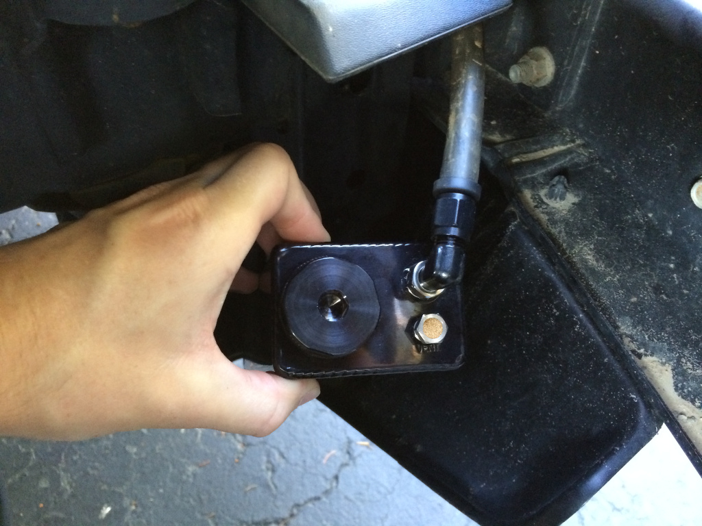
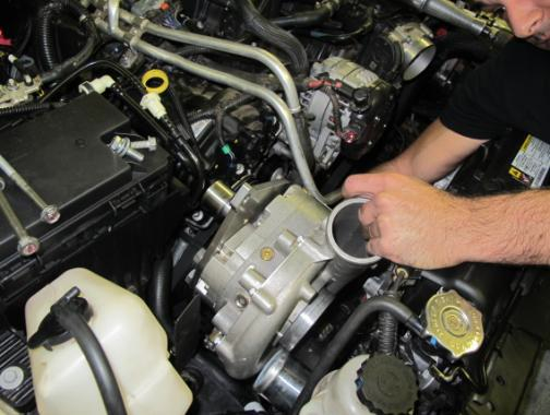
    New location for the coolant reservoir is much better:

    Last edited by UselessPickles; 12-02-2017 at 11:19 AM.

  3. #213
    you will have to remove the two mounting bolts and pull the reservoir out a bit if you want to take the cap off and check the coolant level in it. I would much prefer another semi-transparent plastic container that is easy to visually check, like the one in the RIPP kit.
    You do not need to remove the reservoir to check fluid level. You can just remove the center cover between the grille and the bumper. This will allow access to view fluid level and top off as necessary. Do you have a pic of the Ripp plastic container? i would like to see it...

  4. #214
    Quote Originally Posted by boosted1 View Post
    You do not need to remove the reservoir to check fluid level. You can just remove the center cover between the grille and the bumper.
    I must just have horrible luck with those stupid plastic fasteners that hold the plastic cover down. I usually have to resort to partially or fully destructive methods to remove them. For me, it's quicker/easier to unbolt the reservoir. Have any tips for removing those plastic fasteners?

    Quote Originally Posted by boosted1 View Post
    Do you have a pic of the Ripp plastic container? i would like to see it...
    Here's a couple pics I found online:


    I found the PDF installation guide at one point, but can't find it again now. They have a bracket that mounts using the original bolts on the stock air box support. The reservoir just drops/slides down onto the bracket. It appears to me that they just found an OEM reservoir from some other vehicle that happens to fit in that space, then made a custom bracket for it, but that's just my speculation.

  5. #215
    Thanks jeff for the instructions, i have contaced Dan and he sent me the installation manual but yours better.

    Just finished with installation with couple of issues:

    1- Check engine code P0129 related to map sensor. I have updated the tuner. Might had to clear it and check again but a second issue is there.

    2- A heavy leak between the turbine and the down pipe. (Clamp removed and i can see a space and miss match)

    3- can't figure out the rest of the leak cause the second issue was the big and noisy.

    I am tired now can't think, ill better rest and think later.

  6. #216
    Quote Originally Posted by jeepsking View Post
    A heavy leak between the turbine and the down pipe. (Clamp removed and i can see a space and miss match)
    IMPORTANT: See update at the bottom of this post!

    I found that the connections between the turbine housing, turbo feed pipe, wastegate and downpipe all didn't want to easily match up to each other. I got the best results by doing this:

    1) Loosen all exhaust connections from the turbo back to the head of the engine, including loosening the V-band clamp connecting the the down pipe to the turbine housing, and the 4 bolts holding the turbine to the turbo feed pipe. Loosen the head pipe bolts and ball joints just enough to allow sliding/rotating movement. Loosen everything else more to allow large amounts of movement (especially the 4 bolts holding the turbine to the feed pipe).
    3) Double check that the wastegate is perfectly seated onto the turbo feed pipe, and put the clamp on (squeeze the clamp into place with pliers, but don't tighten yet).
    4) Get the other end of the wastegate firmly seated into the down pipe, and put the clamp on (squeeze the clamp into place with pliers, but don't tighten yet).
    5) Wastegate should be guaranteed to be properly seated and leak-free now.
    6) Mate the turbine housing to the downpipe and partially tighten the v-band clamp. The goal is to have the clamp prevent the joint from separating, but allow it to rotate if necessary. It should be easy get this joint to line up flush because of all the slack in the connection between the turbine housing and the feed pipe. Loosen those 4 bolts more if necessary to get enough slack.
    7) Lightly snug up all 4 bolts (but don't tighten!) holding the turbine housing to the feed pipe. The short flex pipe between the wastegate and downpipe will get flexed/stretched slightly as necessary as these bolts are snugged.
    8) Finish tightening the v-band clamp for the down pipe, and tighten the wastegate clamps.
    9) At this point, the turbo, wastegate and downpipe should be all locked together as one complete assembly, with all joints completely sealed. There should be no other possible orientation of all these interconnected joints.
    10) Loosen the 2 bolts holding the down pipe to the engine. Have someone apply pressure to the turbo to make sure the whole system is shifted as far upward and toward left side of the vehicle as possible as you re-tighten those 2 bolts (reduces contact between the air filter and right-side inner fender liner).
    11) Confirm that the air filter will not be too far forward or rearward, contacting anything (like the trimmed air box support). If necessary, have someone apply pressure forward or rearward on the turbo as you tighten the 4 bolts holding the turbine to the feed pipe.
    12) At this point, the main turbo system should be locked into place where it should be relative to the engine, via the 3 mounting points to the engine. The rest of the exhaust system back to the engine should now just be in whatever orientation is necessary to allow the turbo system to be where it needs to be.
    13) Tighten the pipes to the heads of the engine.
    14) Tighten the ball joints in the exhaust.


    ------------- UPDATE --------------
    Prodigy now has a more detailed and different recommendation for how to install the turbo and pipes. This new method worked better for me. Here's their video:

    ]

    it's important to have another 1-2 pair of hands to help when making the second wastegate connection. I had one person support the weight of the turbo while I laid under the Jeep, reaching up to shift everything around to align the wastegate connection, then another person slilped the clamp over the wastegate connection while I held it in perfect alignment.

    Then when tightening the turbo V-band clamp, do it in stages where you tighten it a bit, then jiggle the connection and tap the clamp with a soft mallet to help get that V-band connection in perfect alignment.
    Last edited by UselessPickles; 12-02-2017 at 11:17 AM.

  7. #217
    Senior Member
    Join Date
    Feb 2014
    Location
    MD/PA line
    Posts
    425
    Quote Originally Posted by UselessPickles View Post
    I found that the connections between the turbine housing, turbo feed pipe, wastegate and downpipe all didn't want to easily match up to each other. I got the best results by doing this:

    1) Loosen all exhaust connections from the turbo back to the head of the engine, including loosening the V-band clamp connecting the the down pipe to the turbine housing, and the 4 bolts holding the turbine to the turbo feed pipe. Loosen the head pipe bolts and ball joints just enough to allow sliding/rotating movement. Loosen everything else more to allow large amounts of movement (especially the 4 bolts holding the turbine to the feed pipe).
    3) Double check that the wastegate is perfectly seated onto the turbo feed pipe, and put the clamp on (squeeze the clamp into place with pliers, but don't tighten yet).
    4) Get the other end of the wastegate firmly seated into the down pipe, and put the clamp on (squeeze the clamp into place with pliers, but don't tighten yet).
    5) Wastegate should be guaranteed to be properly seated and leak-free now.
    6) Mate the turbine housing to the downpipe and partially tighten the v-band clamp. The goal is to have the clamp prevent the joint from separating, but allow it to rotate if necessary. It should be easy get this joint to line up flush because of all the slack in the connection between the turbine housing and the feed pipe. Loosen those 4 bolts more if necessary to get enough slack.
    7) Lightly snug up all 4 bolts (but don't tighten!) holding the turbine housing to the feed pipe. The short flex pipe between the wastegate and downpipe will get flexed/stretched slightly as necessary as these bolts are snugged.
    8) Finish tightening the v-band clamp for the down pipe, and tighten the wastegate clamps.
    9) At this point, the turbo, wastegate and downpipe should be all locked together as one complete assembly, with all joints completely sealed. There should be no other possible orientation of all these interconnected joints.
    10) Loosen the 2 bolts holding the down pipe to the engine. Have someone apply pressure to the turbo to make sure the whole system is shifted as far upward and toward left side of the vehicle as possible as you re-tighten those 2 bolts (reduces contact between the air filter and right-side inner fender liner).
    11) Confirm that the air filter will not be too far forward or rearward, contacting anything (like the trimmed air box support). If necessary, have someone apply pressure forward or rearward on the turbo as you tighten the 4 bolts holding the turbine to the feed pipe.
    12) At this point, the main turbo system should be locked into place where it should be relative to the engine, via the 3 mounting points to the engine. The rest of the exhaust system back to the engine should now just be in whatever orientation is necessary to allow the turbo system to be where it needs to be.
    13) Tighten the pipes to the heads of the engine.
    14) Tighten the ball joints in the exhaust.

    I hope After going about it differently the first go round..this is almost exactly how we achieved success in alignment. Excellent write up that I hope modifies/supplements future versions of Prodigy's install manual.

    Your Steps 6 and 10 were critical steps for our install, having done it differently the first time. Adding to step 14, we definitely had to use the impact to get a nice tight seal on those ball joints. I love those joints for their ability to flex around and still get a solid seal.

  8. #218
    As Snarf said: your instructions are much superior and professional to PD installation.
    i will try these tomorrow as today is a family day. My way of driving is extreme, hope i won't bend any exhaust.

  9. #219
    Ok. I am done with the install. Thanks Jeff and everyone. Started the vehicle and got several codes (check engine) manage to clear them. Started driving and had a bad throttle response with another check engine code P2173 (throttle actuator control system - high air flow detected. Cant drive it Had to put my car on a recovery to get it home . I will contact PD , i might done something wrong.

  10. #220
    A vacuum leak can cause that code. Double check all hoses that connect to the intake manifold. I really hope you didn't mangle any of the intake manifold gaskets while reinstalling it.

Posting Permissions

  • You may not post new threads
  • You may not post replies
  • You may not post attachments
  • You may not edit your posts
  •