Close

Page 10 of 45 FirstFirst ... 8910111220 ... LastLast
Results 91 to 100 of 449
  1. #91
    Ok... back to the install.

    Next up is to install the oil feed line for the turbo. You'll be working in this area:


    That dark abyss is only that dark because it was a bright sunny day with harsh shadows. I believe that's the oil cooler just below the yellow circle. What you care about is the oil pressure sensor:


    I think the smaller sensor in the foreground is the oil temperature sensor, but I'm not sure. It's the big sensor underneath it that needs to come out. This is where I lost several hours of time due to not having the right tool. It's tight in that space, and I didn't have a wrench large enough. I have an adjustable crescent wrench that just barely opens wide enough to fit on it, but the wrench is too chunky to get in there and get a good grip. I ran around to a couple stores looking for a wrench that would fit. The biggest wrench I found was 1-1/16", and it was a bit too small. I'm, thinking it might need a 1-1/8" wrench.


    After failing to find a wrench, I re-visited the adjustable crescent wrench. I determined that the coolant hose underneath the sensors was blocking my access to get it firmly around the sensor nut. With some patience working in that tight space with needle nose pliers, I got the hose clamp off, then was able to get the hose off and out of the way. Of course, coolant spilled out into the valley of the engine, so I had to try to soak it up with paper towels, then dilute it with water and soak it up again. With the hose out of the way, I was just barely able to get the adjustable wrench onto the sensor and had just enough room to loosen it 1/6th of a rotation at a time. Note that while the smaller sensor seems to be in the way, you CAN attack the oil pressure sensor at an angle and work around the smaller sensor.

    Once the oil pressure sensor is out, you basically install a T-fitting in its place, install the oil pressure sensor onto the end of the T-fitting, and compression fitting to the top of the T, then attach the oil feed line to the compression fitting:


    Teflon tape (like PTFE plumber's thread tape) is used on all threaded connections here, except for the oil line itself, because that's a compression fitting. Search online for how to properly use thread tape (need to wrap it in the correct direction, about 4 times around).

    Before you snug up the oil line connection, make sure you have it routed nicely between all the nearby wire harnesses, hoses, etc. I'll post photos later of the completed install, trying to show how I ended up generally routing everything. I'm a bit OCD about routing things nicely, so I actually ended up re-routing some things a few times until I was happy with it.

    Such a simple and innocent looking step of the install, and it took me 3+ hours to complete between trying different tools I had, running to stores, cleaning yet another coolant spill, and all the tedium of working in that small space. I felt unstoppable once this step was over.

  2. #92
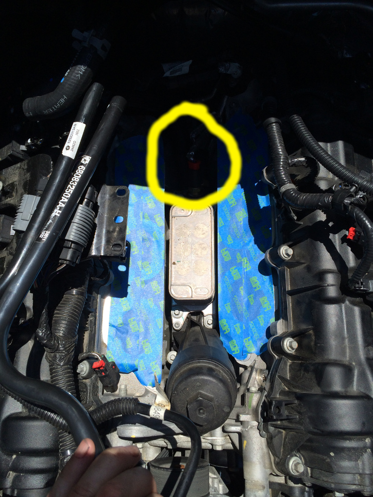
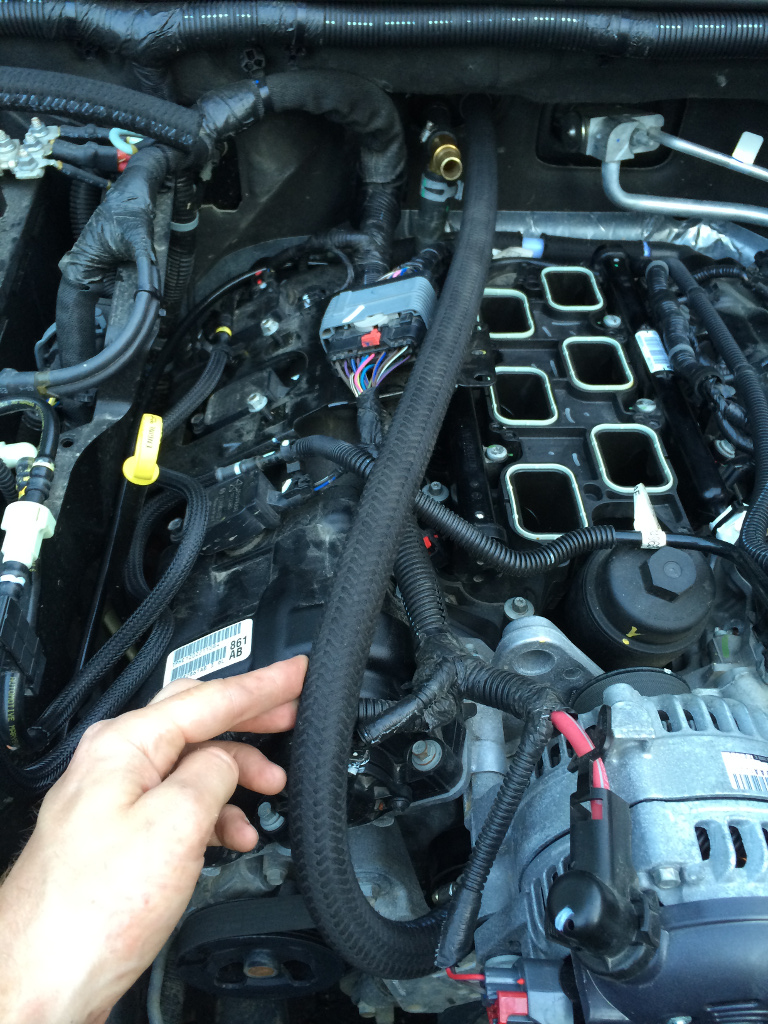
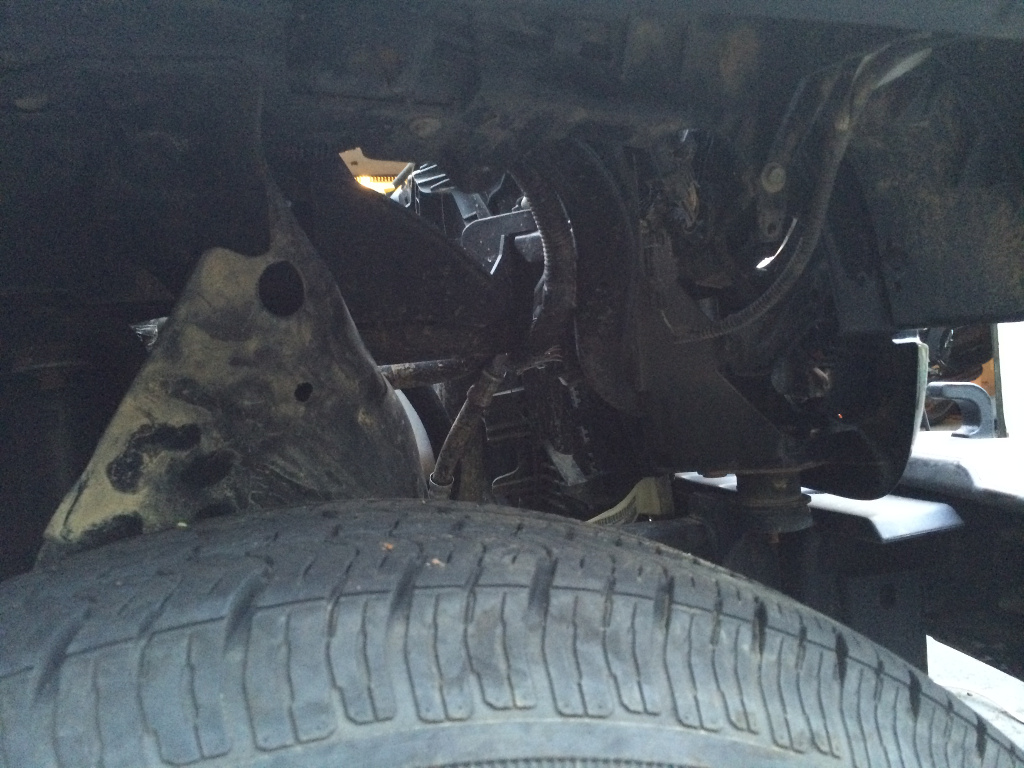
    See these plastic pipes with rubber connectors (the top of the picture highlights approximately where the pipes run behind everything)?


    You can actually pull those out and get them out of the way earlier than instructed, whenever is convenient. They'll be easiest to remove once the upper and lower intake manifold are removed. Those are part of the crankcase ventilation system.

    One pipe runs from the passenger side valve cover to the intake manifold. When idling or cruising, the intake manifold creates vacuum through the PCV (positive crankcase ventilation) valve and sucks nasty air out of the crankcase (blow-by unburnt fuel, water vapor, etc). Slight vacuum in the crankcase keeps oil seals happy, and sucking out nasty junk keeps oil more pure, avoiding corrosion, sludge, etc. I will refer to this as "the PCV pipe".

    The other pipe runs from the driver side valve cover to the air box. This is just a breather; no significant vacuum is applied to this pipe by the intake system, but it runs to the air box in stock configuration to be recirculated into the intake to reduce emissions. I will refer to this as "the breather pipe".

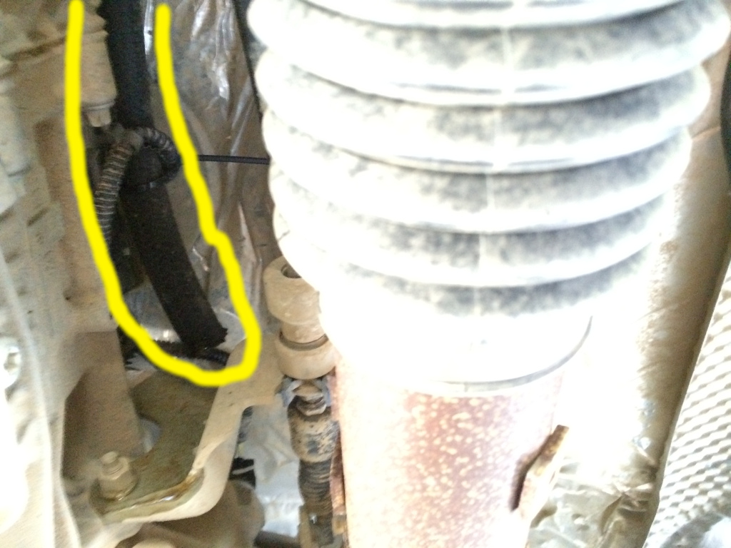
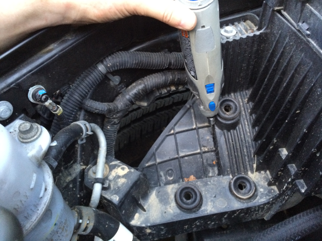
    The turbo kit replaces these pipes. The breather pipe is simply replaced by a long hose that runs down behind the engine, along the top of the transmission, with the end of the hose zip-tied in place to vent to atmosphere under the vehicle. The EPA won't like this, but Prodigy explicitly chose to go this route rather than maintain the recirculating behavior. Hot air with some oil vapor, unburnt fuel, water vapor, etc., flows out of this hose when running boost, because there is significantly more blow-by past the pistons with boost, and that extra pressure in the crankcase needs to escape somewhere. That hot contaminated air interferes with tuning for power. For example, oil vapor reduces the effective octane rating of the fuel, making it more prone to pinging/detonation. Rather than tune more conservatively (less power) and/or require higher octane fuel (already requires 91 minimum), Prodigy has opted to avoid the problem altogether and slap the "for off-road use only, wink, wink" label on the turbo kit.

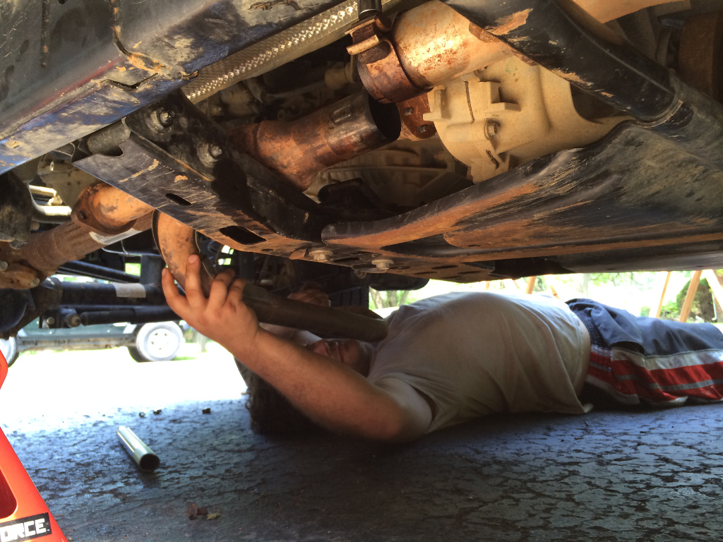
    It's hard to get a good picture of this breather hose, but here's the end of it after installation:


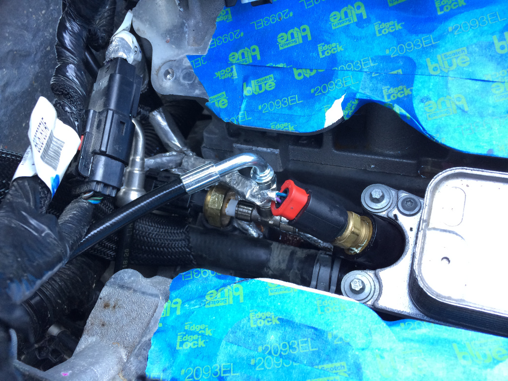
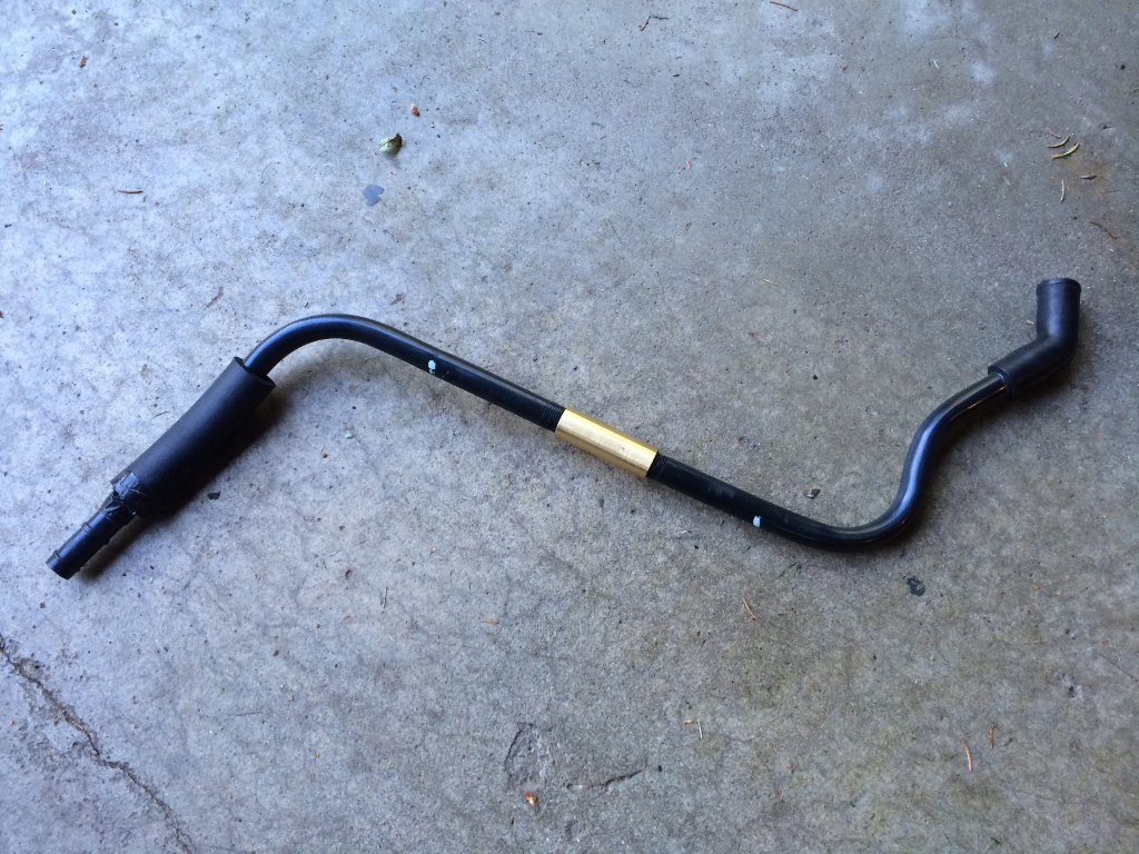
    The PCV pipe is replaced by a hose with a check valve about at its mid point. The check valve prevents the crankcase from seeing positive boost pressure from the intake manifold.


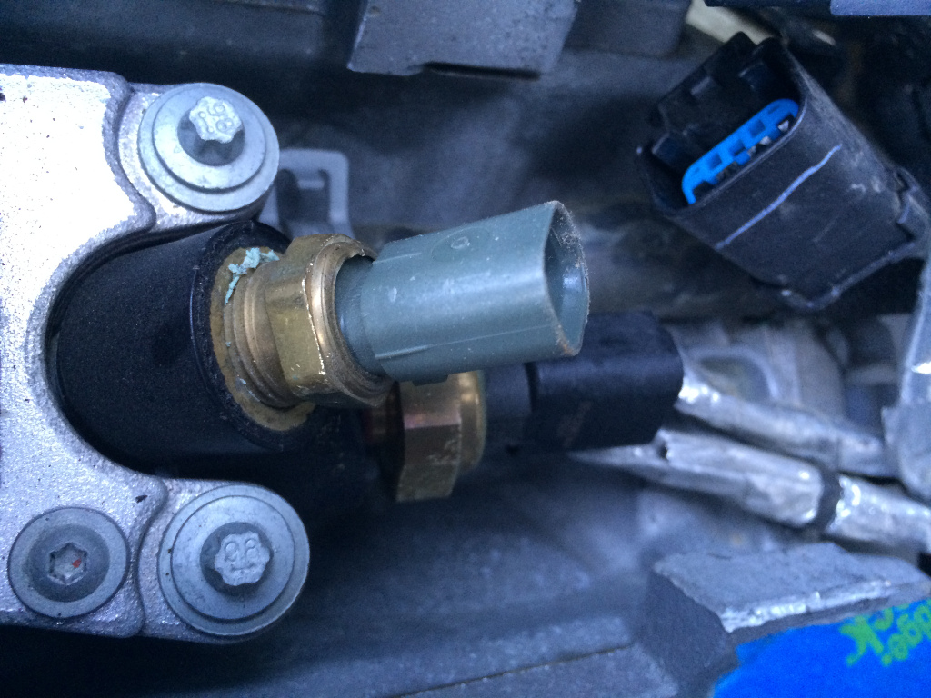
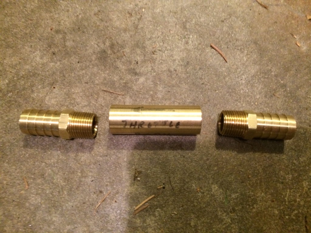
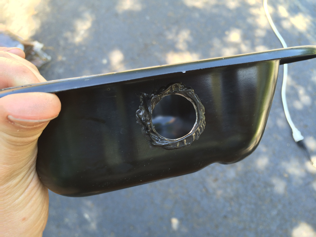
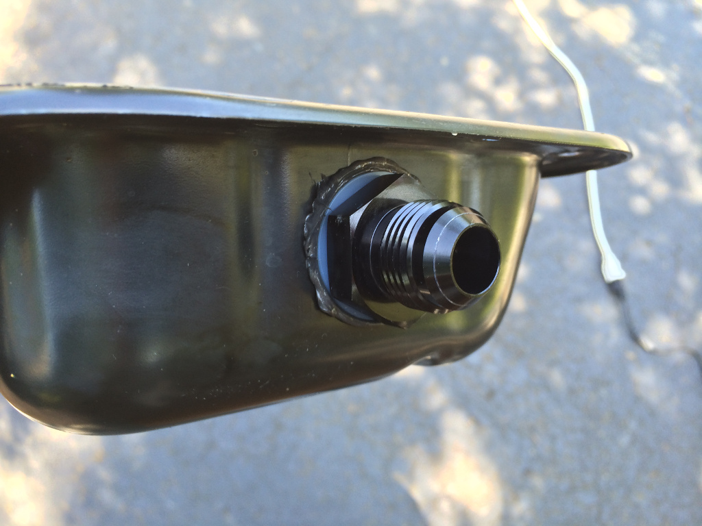
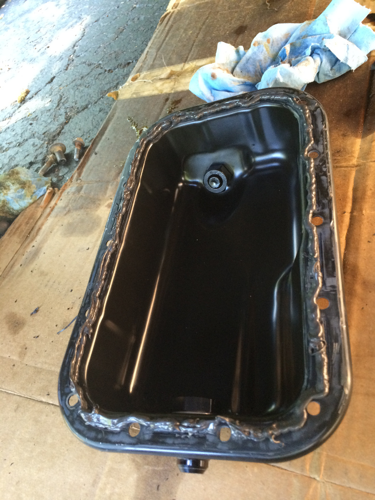
    However, I made the observation that the check valve has the hose fittings threaded into it:


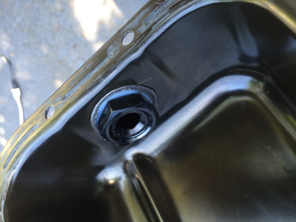
    And the diameter of the original plastic PCV pipe is a very close match to fit into the female threads of the check valve. So I decided to put a little extra effort into making my install just a bit cleaner:


    Those are 3/8" pipe threads to match the threads in the check valve. I was able to borrow a rental thread cutting die at a local hardware store for $5 to get the job done at the counter in-store without paying any rental deposits, etc. If I had taken it home to use it, there would have been a $50 deposit, and the rental fee was $8. Just make sure you thoroughly clean any plastic shavings/dust from the cutting and threading. Don't want to suck that into your engine. Male pipe threads are cut with a taper, so it's a combination threaded/compression fitting. Because of this, and especially because the pipe is plastic, the pipe and check valve can be threaded tightly together and form an air-tight seal without any kind of thread sealant.


    I like to keep as many things as possible appearing OEM, or at least OEM-like, and not obviously modded. You'll have to wait to see the modded PCV pipe installed, because there's plenty of other things that need to happen with the turbo install first


    NOTE: The ventilation hoses/pipes are easily accessible after the install is complete, so you can start by following Prodigy's instructions, then customize it as I did at a later time if you decide to do so.


    UPDATE: This modded PCV pipe needs a redesign due to annoying noise: http://jeeplab.com/showthread.php?13...ull=1#post2112

    UPDATE: New revision successfully got rid of annoying noise: http://jeeplab.com/showthread.php?13...ull=1#post2116

    UPDATE: Crankcase ventilation solutions are still being tested by Prodigy, so what I have described here is not final.
    Last edited by UselessPickles; 07-09-2014 at 03:20 PM.

  3. #93
    Oops, I went out of order a bit. The following stuff comes in the instructions before messing with the crankcase ventilation stuff.

    Here's two short hoses left over from that aluminum coolant pipe assembly that was removed. These connect to the heater core for blowing hot air in your face on a cold morning:


    These get trashed. Rather than fighting to remove them normally, the instructions give you the easy way out: carefully cut a slit on the ends of the hoses with a utility knife, then peal the hoses off:


    After this, the instructions have you install the oil feed line at the oil pressure sensor (which I already covered), then the instructions have you install the new fuel injectors in the lower intake manifold (which I also already covered).

    Next, re-install the lower intake manifold. I don't have a specific picture for this. It looks the same re-installed as it did before it was removed.

    Then the crankcase ventilation stuff (which I already covered).

  4. #94
    Next up: starting to hook up the new hoses that replace the aluminum coolant pipe assembly for the heater core.

    There's a couple steps crammed into one picture here:


    The obvious one is the hose I'm pointing at, which connects to the driver-side heater core fitting.
    Less obvious is that a short hose and T-fitting are connected to the passenger-side heater core fitting. One of the original coolant hoses is connected to the bottom of the T.

    And a long hose is connected down here in the front of the engine where one of the aluminum pipes used to connect:


    The other end of the hose will eventually connect to that T fitting at the heater core, but it is just set aside out of the way for now, because it will have to be carefully routed around turbo components before being connected. Hose clamps are used at all connections involving these coolant/heater hoses. you can also see a lonely end of an oil feed line in that picture, just waiting for a turbo to connect to.

  5. #95
    Time to make room for the turbo's air filter:


    The air box support is in the way, so it needs to be trimmed. I used a Dremel with a routing bit. Be careful not to cut through other nearby things, like a wiring harness and the fender liner. I actually unfastened the front half of the fender liner and folded it out of the way:


    The instructions don't tell you to fold the fender liner out of the way until much later when it's time to install the air filter (yes, the air filter must be installed through the wheel well). I found that it was very helpful to fold it out of the way now, and leave it folded out of the way for better access/visibility in the area where the turbo will go.


    After trimming the air box support, I cleaned up the cut edge with a sanding drum bit in the Dremel.

  6. #96
    Check out my newly blacked-out pipe and clamps:


    No expensive ceramic or powder coatings. Just a $4 spray can of high-temp matte black paint for BBQ grills

    Also a water-repellent air filter wrap to protect the air filter from splashes of water/mud.

  7. #97
    So much info!

    Pickles... YOU ROCK.

    Now. Im about to get the handcuffs off. Prodigy has bought the plane tickets, and we are expecting them up here on friday. The 11th.

  8. #98
    Can't wait to start hearing your feedback and comparisons to the superchargers

  9. #99
    Time to drill a hole in the oil pan!

    Drain the oil. You might as well change the oil filter now too.

    Then remove all the oil pan bolts. On two corners, there are nuts instead of bolts. Loosen those nuts to the ends of the studs, but don't remove them yet. These will hold the oil pan from suddenly falling once you get it pried loose.

    There's an exhaust hanger that we found to be in the way of prying the oil pan off. It needs to come off later anyway, so we just removed it at this point:


    All the oil pan bolts are removed in that picture, and you can see one of the nuts at the left corner. Next, just very carefully pry the oil pan off, trying not to bend it. It's stuck in place with gasket material. We used a flat blade screw driver and a hammer, tapping it between the pan and the engine, small amounts at a time, working around the whole oil pan.


    Have something under the jeep to catch the oil that will be dripping out of the engine while the oil pan is off.

    I went slightly out of order with oil pan cleaning steps, because I'd rather do one thorough cleaning at the very end after doing all things that can make a mess. I wiped out excess oil from the pan to avoid creating more mess, but didn't try to thoroughly clean it right away. All that nasty gasket material needs to come off both the engine and the oil pan. I used a razor blade scraper and some patience:


    Then use one of the washers from the oil return fitting to plan where you'll drill a hole in the oil pan. It goes on the front, about in the middle (between two bolt holes), and as high up as you can go while keeping the washer on a completely flat surface.


    I used a screw or nail just to mark the center of the hole, then used a very small drill bit to drill a pilot hole before attacking the oil pan with the 7/8" hole saw bit.


    Then the rough edges of the hole need to be cleaned up and smoothed. I used a grinding bit in my Dremel. Now that you're done creating sealant shavings and metal shavings, it's time for a thorough cleaning. Running water, a rag and dish soap worked well for me. Dry it thoroughly, then time to install the oil fitting.


    Sealant (oil resistant silicone gasket maker) on both sides of the hole:


    Instructions on the tube of sealant say to let the sealant partially cure for a short time (I think 20 minutes) before assembly.


    After snugging up the fitting, wipe the excess sealant away on both sides. Then apply sealant to the oil pan.


    Let it partially cure again before installing the oil pan.


    Don't refill the oil yet
    Last edited by UselessPickles; 07-06-2014 at 08:31 PM.

  10. #100
    Now to remove the stock exhaust components.

    First, the catalytic converter pipes come off:


    I didn't get any pictures of the removal process. Those are mounted to each head of the engine.

    Disconnect the O2 sensor wiring first.

    The bolts at the lower end of those pipes (connecting them to the Y-pipe) were a mixed bag. I think 3 of them came out no problem, but we gave up on one and used a sawzall. Those bolts aren't reused with the turbo kit, so don't feel bad about using destructive removal procedures.

    IIRC, 3 of the bolts on each head were accessible through the wheel well by just sticking your hand under the fender liner. Some of them accessible with a 1/4" socket wrench (maybe with a small extension), and some with a simple wrench. At least one lower bolt on each side was only accessible (as far as we could figure out) from underneath the jeep with a simple wrench and some contortion. It's VERY cramped in there, but it is possible. Choose the friend with the smallest hands to do this part.

    Only the top two bolts on each side come completely out. The bottom two just need to be loosened.

    With the bolts removed and loosened, the fun doesn't end. There's almost not enough room to get those pipes out. It just took some experimentation of twisting and wiggling the pipe into different orientations, and finally forcing one of them just a little bit when an O2 sensor was getting barely hung up somewhere. I just confirmed that none of the wires were about to get pinched before giving it the final nudge to break it free.

    Keep the O2 sensors where they are for not. You'll want to transfer them over to their respective locations on the new exhaust system later (after all the new pipes are installed).

    And finally, the y-pipe needs to come out. The instructions make it sound like it will be very difficult, but it was actually the easiest part of the exhaust removal for us. This may have been due to the fact that we had earlier thoroughly soaked the pipe connection with PB Blaster to help break up corrosion.


    The trickiest part for us was the stupid exhaust clamp:


    WHY is the nut ON TOP? As you can see, we ended up popping the pipe out of the exhaust hanger so we could get a deep-well socket onto the nut. Normal human strength was not enough to get that nut to budge, though. Not even after multiple PB Blaster soakings. We ended up sliding the handle of a jack (essentially a long pipe) over the handle of the ratchet for more leverage, and the nut didn't put up much fight against that.

    With the clamp loosened, the y-pipe easily twisted out (again, probably thanks to all the PB Blaster that had soaked in for hours).


Posting Permissions

  • You may not post new threads
  • You may not post replies
  • You may not post attachments
  • You may not edit your posts
  •