


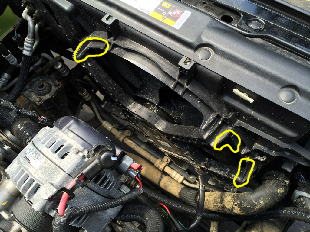
Now to remove the stock exhaust components.
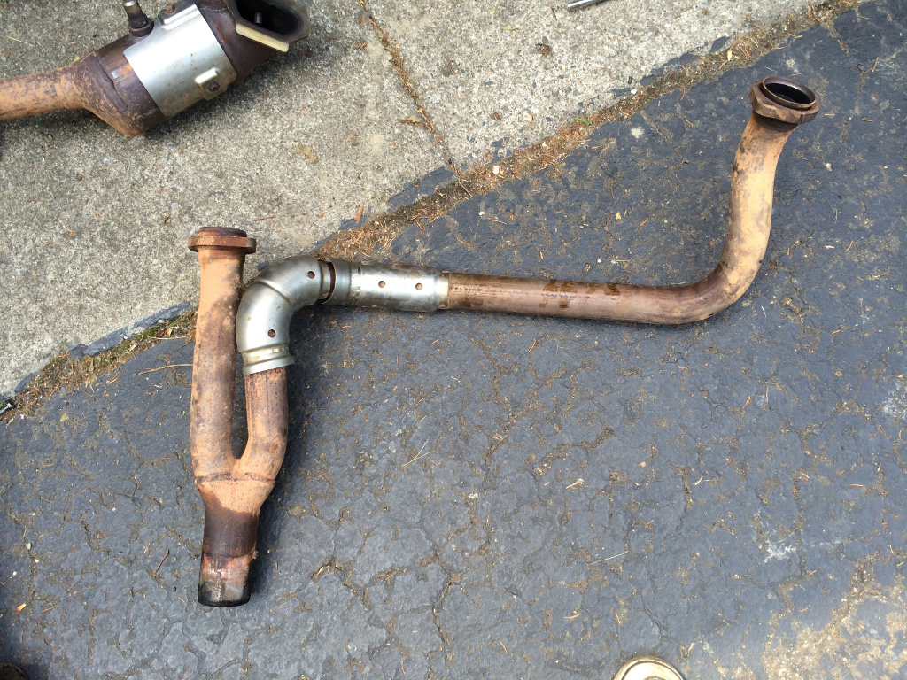
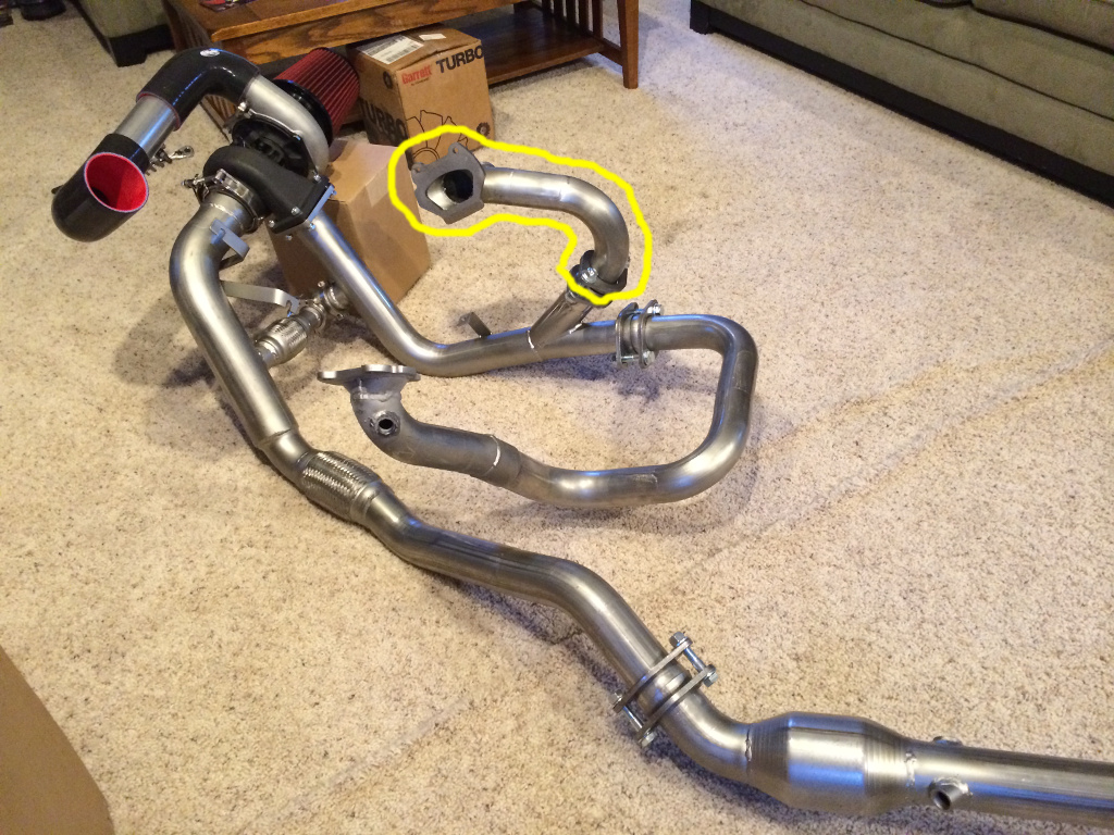
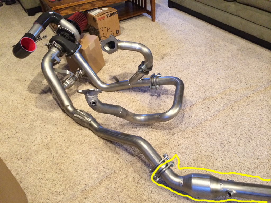
First, the catalytic converter pipes come off:
I didn't get any pictures of the removal process. Those are mounted to each head of the engine.
Disconnect the O2 sensor wiring first.
The bolts at the lower end of those pipes (connecting them to the Y-pipe) were a mixed bag. I think 3 of them came out no problem, but we gave up on one and used a sawzall. Those bolts aren't reused with the turbo kit, so don't feel bad about using destructive removal procedures.
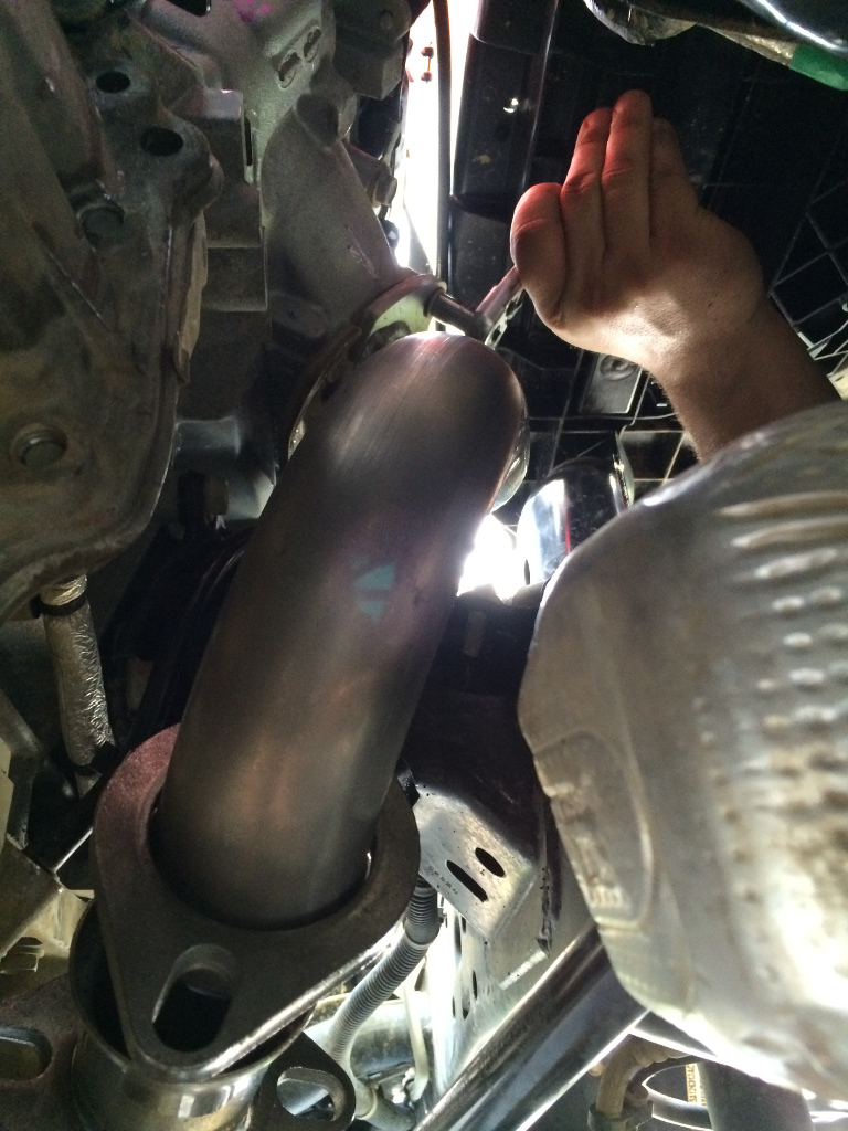
IIRC, 3 of the bolts on each head were accessible through the wheel well by just sticking your hand under the fender liner. Some of them accessible with a 1/4" socket wrench (maybe with a small extension), and some with a simple wrench. At least one lower bolt on each side was only accessible (as far as we could figure out) from underneath the jeep with a simple wrench and some contortion. It's VERY cramped in there, but it is possible. Choose the friend with the smallest hands to do this part.
Only the top two bolts on each side come completely out. The bottom two just need to be loosened.
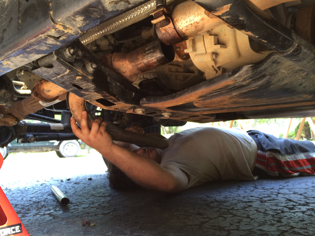
With the bolts removed and loosened, the fun doesn't end. There's almost not enough room to get those pipes out. It just took some experimentation of twisting and wiggling the pipe into different orientations, and finally forcing one of them just a little bit when an O2 sensor was getting barely hung up somewhere. I just confirmed that none of the wires were about to get pinched before giving it the final nudge to break it free.
Keep the O2 sensors where they are for not. You'll want to transfer them over to their respective locations on the new exhaust system later (after all the new pipes are installed).
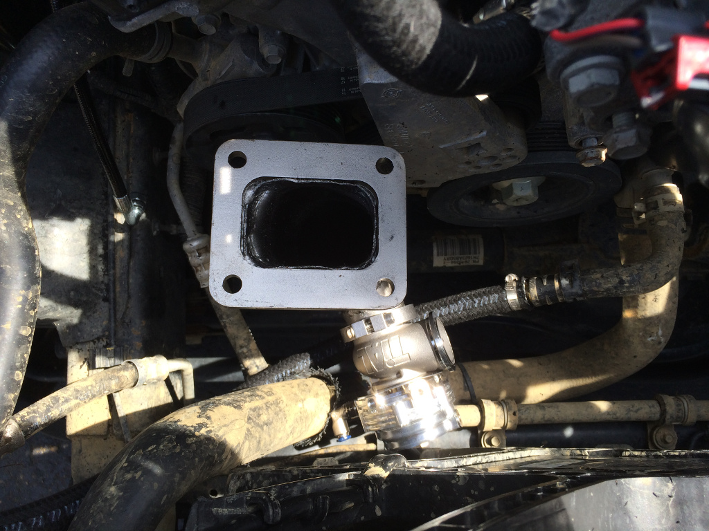
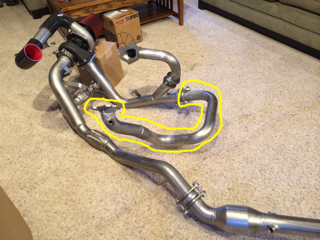
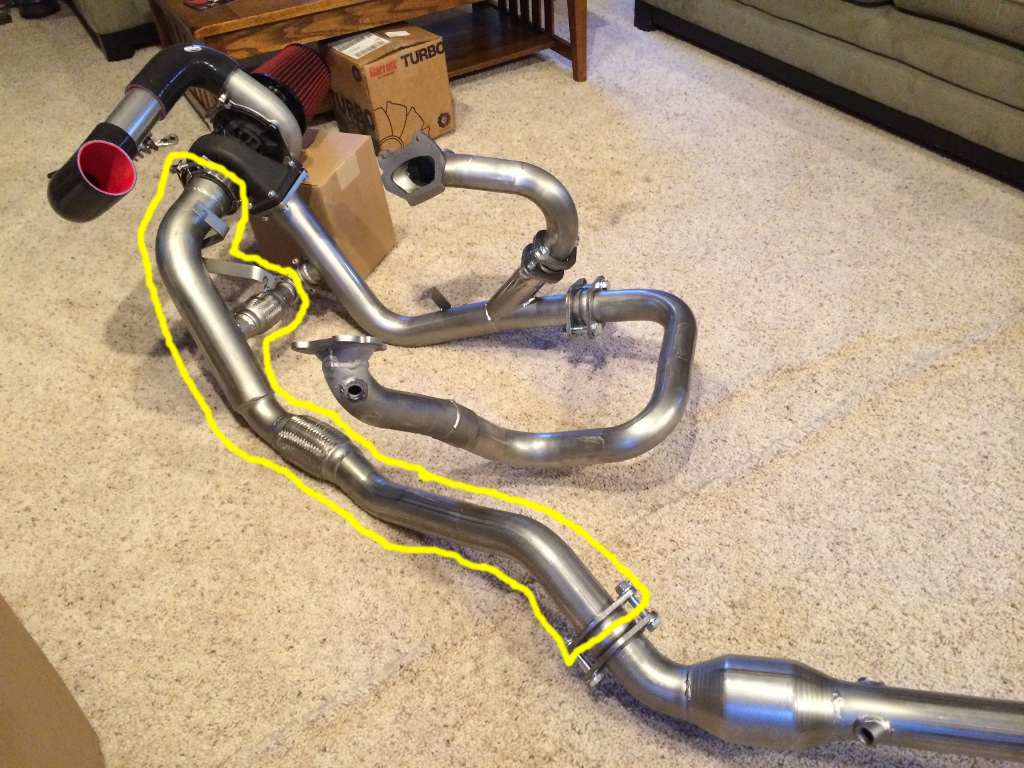
And finally, the y-pipe needs to come out. The instructions make it sound like it will be very difficult, but it was actually the easiest part of the exhaust removal for us. This may have been due to the fact that we had earlier thoroughly soaked the pipe connection with PB Blaster to help break up corrosion.
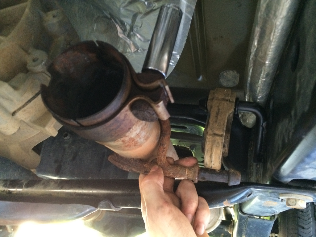
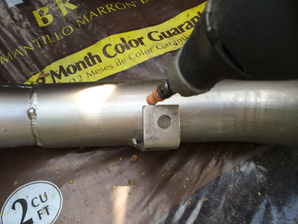
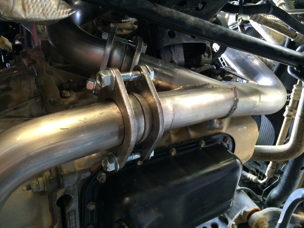
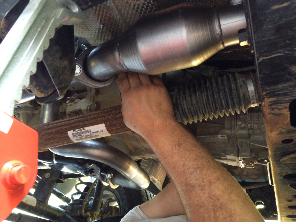
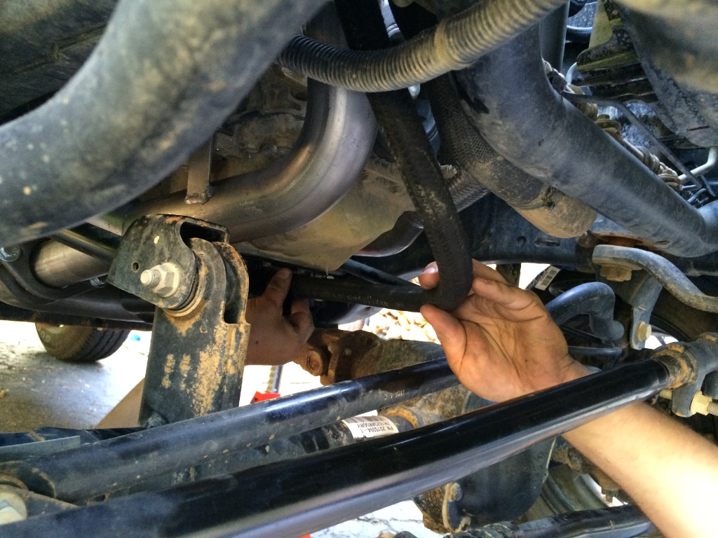
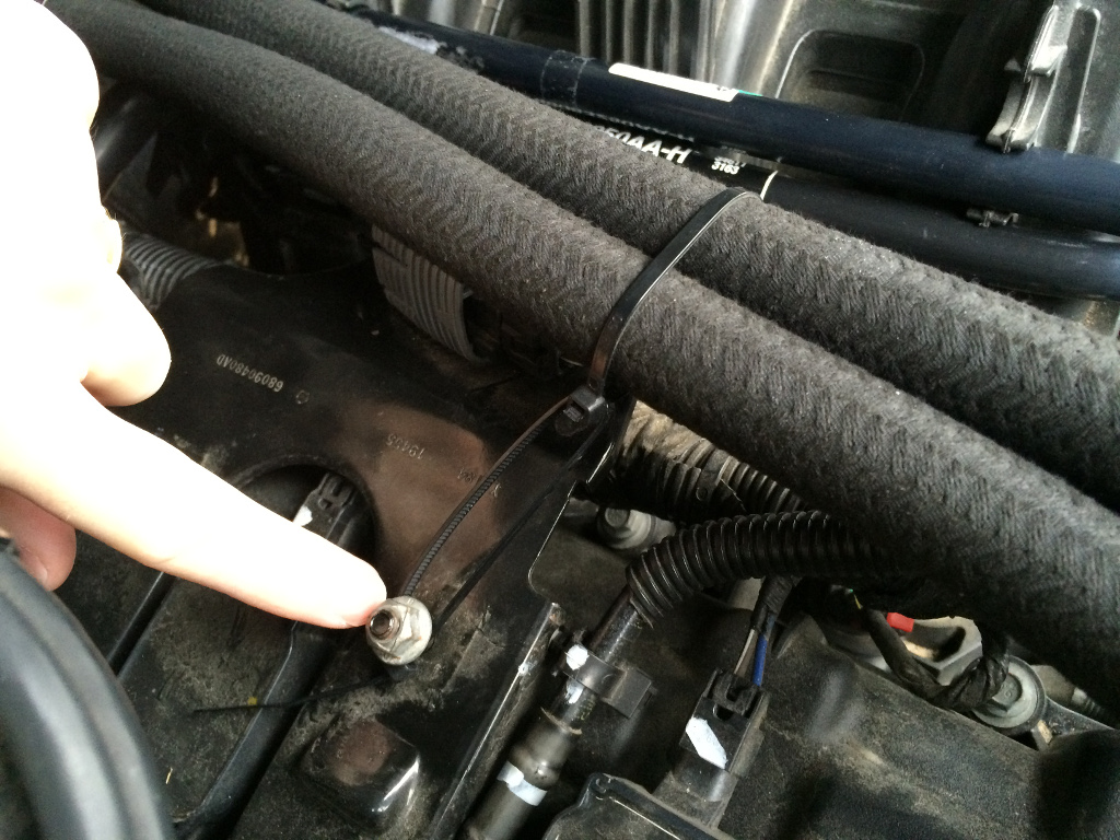
The trickiest part for us was the stupid exhaust clamp:
WHY is the nut ON TOP? As you can see, we ended up popping the pipe out of the exhaust hanger so we could get a deep-well socket onto the nut. Normal human strength was not enough to get that nut to budge, though. Not even after multiple PB Blaster soakings. We ended up sliding the handle of a jack (essentially a long pipe) over the handle of the ratchet for more leverage, and the nut didn't put up much fight against that.
With the clamp loosened, the y-pipe easily twisted out (again, probably thanks to all the PB Blaster that had soaked in for hours).


 Reply With Quote
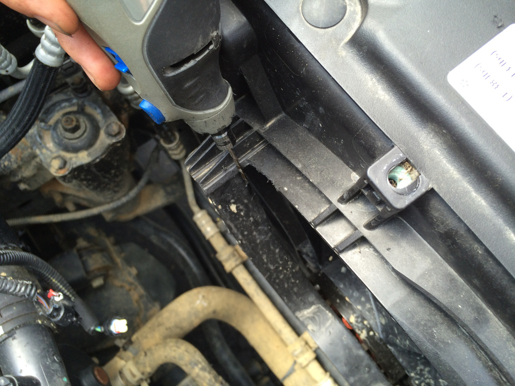


Connect With Us