


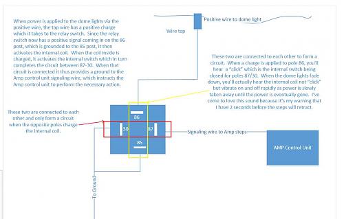
Okay, here's a little diagram. Now, a WARNING!!! I'm creating this from memory, so I may not have the correct wires on the correct posts of the relay switch, but this should get your installers close. I was able to figure this out with nothing but a $5 circuit tester that I would either ground or attach to a positive signal and then touch various parts of the relay as I had the relay hooked up to the ground or amp signaling wire. The point is, any installer worth their salt should be able to look at this, grab a relay, grab a circuit tester and figure it out if what I have drawn up here is not 100% accurate, because the idea itself is so damn simple it's retarded. You have a relay that receives a signal, the relay in turn activates an internal switch that completes the circuit on the opposing posts. When you complete the circuit on the opposing posts, you complete it to a source and destination that you want paired together, (say a signaling wire to a ground, as in our example here, though it could have been external lights positive wire to a 30amp positive feed from the battery so the lights turn on.)
Hope this helps, and as I said before, send me pics of your relay switch and I'll try to help out more.

 Reply With Quote

Connect With Us