


Jesse's Girl will be back on the dyno eventually. I'll be doing some axle work with some Yukon kit in the rear, and hopefully a new driveshaft. Once she's up and running right again, I'll sticker her back on the rollers and see what's up.


Jesse's Girl will be back on the dyno eventually. I'll be doing some axle work with some Yukon kit in the rear, and hopefully a new driveshaft. Once she's up and running right again, I'll sticker her back on the rollers and see what's up.
More data! I'll send you a PM with my email address so you can send me some logs.
This page has a link to download the Diablosport data viewer, which is used to view the data logs: https://www.diablosport.com/products...a-logging.html
It's in the section titled "Integrated PC Logging Software".
NOLA: Bad news...
You're only getting 7.5 psi peak boost!
Worse news...
Your boost doesn't hold steady after it peaks. It falls off to only about 6.7 psi boost near red line.
I suspect that your wastegate boost sensing line is still hooked up in the stage 1 configuration (connected directly to the turbo outlet). For stage 2, it's supposed to be teed into a vacuum line that connects to the intake manifold (per Prodigy's instructions).
Originally Posted by UselessPickles

Thats not good! Thanks for the Info. Im on the hunt now for the escaping boost.. Can you show me a picture of your set up for the stage 2 wastegate configuration? For a reference point.. I had the shop install mine so i dont know what cross reference it to. Thanks.
Go back to this post to see some details I already covered about where the wastegate line gets connected with stage 2, and where it really should get connected: http://jeeplab.com/showthread.php?14...ull=1#post2740
Quick review...
This link has cool info and pictures to explain stuff: http://www.miataturbo.net/diy-turbo-...eed-ebc-47532/
The wastegate should be connected to position "B", between the intercooler and the throttle body.
Stage 1 has the wastegate connected to position "A". Since stage 1 has no intercooler, this is fine. Without an intercooler, there is no significant difference in pressure measured from position "A" or position "B".
NOLA's problem is that he has the intercooler now, but his wastegate is still connected to position "A". He is experiencing lower peak boost as well as "boost sag", which is explained in the link above.
The official instructions for stage 2 have you connect the wastegate to position "C". This post explains why position "C" is bad: http://www.miataturbo.net/diy-turbo-...32/#post574757
For my install, I used one of these to add a boost source at position "B" for my wastegate:
http://www.atpturbo.com/mm5/merchant...egory_Code=BCS
Here's the boost source for my waste gate:
I zip-tied the waste gate line to the BOV line, and at two points on the radiator fan shroud. One of the points is simply tied to an existing wire that is secured to the fan shroud. I had to drill a small hole through an "arm" of the fan shroud closer to the BOV to add a zip tie there and hold the wastegate line away from the exhaust down pipe.
And here's how my BOV line is teed into an existing vacuum source on the intake manifold:
is there a standard solution to these varying boost pressures?
There's no standard solution. First you need to know how much boost you're supposed to have and what the acceptable variation is among properly installed systems. If you're off by an unreasonable amount, then search for the cause and fix itToo much boost is most likely caused by a leak in the wastegate boost sensing line. Too little boost is most likely a boost leak in the intake system between the turbo and the throttle body.
NOLA's problem was easy to diagnose just from looking at the shape of his boost curve in his data log. Incorrect wastegate setup.
We still don't have a straight answer for what the normal amount of boost is yet. Snarf and I are off by 1 psi from each other, which seems like more than an acceptable variance to me. I'm interested in seeing how much boost NOLA has after correcting his wastegate setup.
If NOLA gets about 9 psi like Snarf, then I will suspect I have a boost leak, and I'll have to perform a boost leak check: fabricate a way to hook an air compressor to the turbo inlet so I can pressurize the full intake system and search for leaks at all the connections with soapy water.
If NOLA gets 8 psi like me, then there's a few possibilities:
1) Maybe there's a 1 psi pressure drop across the throttle body. Snarf's wastegate boost source is downstream of the throttle body. Mine is upstream of the throttle body, and NOLA will be duplicating my setup. If there's a pressure drop across the throttle body, then the downstream boost source will result in more boost in the intake manifold. I could test this easily by temporarily rearranging things so that my wastegate is hooked up similar to Snarf's.
2) Maybe Snarf has too much boost. I had about 1 psi extra boost with stage one, which I suspect was caused by a mangled o-ring on one of the fittings for the boost sensing line for the wastegate. If the test for option 1 above fails, then I would as Snarf to double check that all his wastegate boost sensing line connections are tight.
3) Maybe NOLA and I BOTH have boost leaks. If tests for option 1 and 2 both fail, then I'll work on a boost leak test.
If everything checks out and it turns out there really is a wide normal variation in boost across different installs, then a simple manual boost controller could be used to get a lower boost system up to 9 psi. They basically introduce a controlled leak into the wastegate boost sensing line to trick the wastegate into "seeing" less boost so that it opens later and at a higher actual intake manifold boost level.
Jeff. Thanks for sharing your knowledge. I have a question related to the AFR sensor. Where is the best place to install it in this setup.
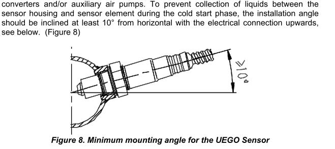
From searching, it seems like a general guideline for wideband AFR sensor location is that it should be after the turbo to avoid exposing the sensor to the high exhaust temps before the turbo. Another general guideline is that you should avoid mounting it too far downstream because it takes time for exhaust to travel through the pipes, and you want as little lag as possible between exhaust exiting the engine and causing a reading on the sensor.
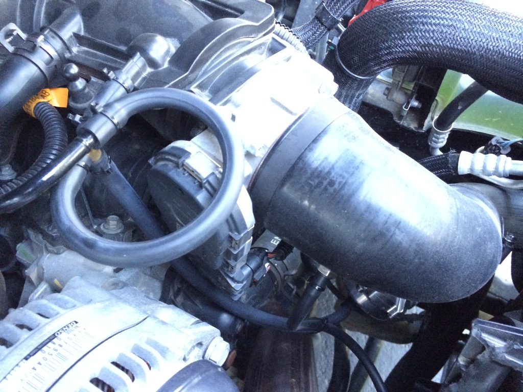
If I were to add a AFR sensor, I would probably put it on the downpipe, after the downward bend, so that the wiring could be routed up between the alternator and throttle body. Basically, somewhere on the part of the downpipe that is visible from above, to the right of the downward bend that is right in front of the alternator:
Just find a spot that fits well, lets you route the wiring nicely, and don't mount it horizontal or below horizontal:
Thanks Jeff. That really helps. I will be installing my kit next week. Hope so.
 Posting Permissions

 Reply With Quote


Connect With Us