


 Reply With Quote
Awsome thread. You are toing to change to stainless tube for everything?

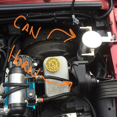
Here's what it looks like from above.

Awsome thread. You are toing to change to stainless tube for everything?
Keep it coming. Great info.
Im on the edge of my seat. Your going to bend that stainless pipe?
Yes. I'm going to bend the stainless tubing myself. I'll post pics of the process.Originally Posted by JeepLab

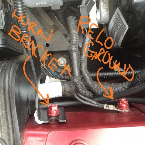
OK. I was able to get back at it today. First step - relocate the horn. The horn bracket (in an earlier picture) is mounted to the inside of the driver's side fender. Just forward of the mounting stud is another stud with a ground. I'm going to swap the ground to the original horn location, modify the horn mount bracket and relocate it to the forward stud.
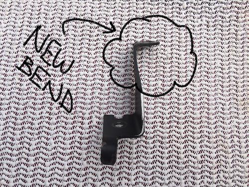
The final mods to the horn bracket took a few trials (and errors). But ultimately this is how it went. You need to remove a portion (shown), re-bend the tab that holds the bracket straight and re-bend the end to turn the horn mounting hole 90 degrees. I was tempted to just cut the support tab off but thought better of it because it really does do a job so I kept it.
Like so:
Final shape:
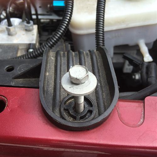
Before mounting the horn I decided to move the windshield washer hoses downward so they would more easily clear the can. To do this I had to loosen the ABS platform bolt that attaches to the top of the fender. With this bolt out I was able to just move the washer hoses down to a clear area.
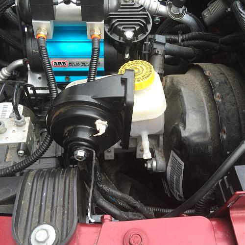
And the horn goes into it's new location. I could have mounted the horn much lower into the fender well. But I figured "high is dry" should be my philosophy under the hood.
Next I mounted the catch can. I removed the bracket from the can. I used the bracket and a center punch to drill a pilot hole for the bolt location. Then I used a step-drill to enlarge the hole in the sheet metal to fit the mounting bracket for the catch can. All of this will be de-mounted and painted or treated before I'm finally finished. First, however, I want to get it all to fit and work.
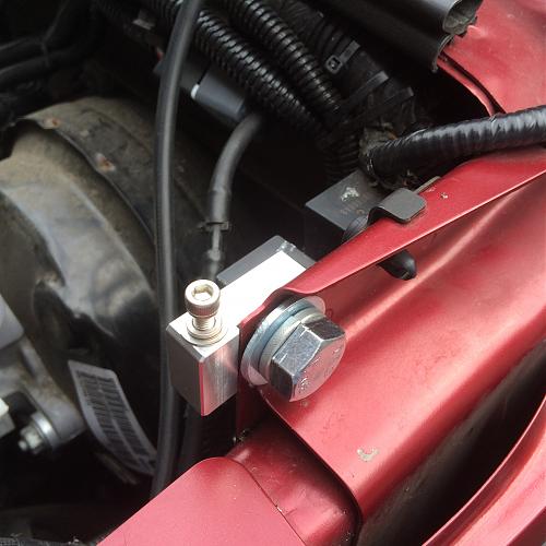
And the catch can finally goes in.
 Posting Permissions

Connect With Us