Close

Page 21 of 43 FirstFirst ... 11192021222331 ... LastLast
Results 201 to 210 of 449

Hybrid View

Previous Post Previous Post   Next Post Next Post
  1. #1
    Quote Originally Posted by Timmy View Post
    So by this logic, me putting on a big puffy down jacket should make me cooler
    Close... except not at all. Increased surface area is not the only criteria for cooling more efficiently. A big puffy down jacket uses materials designed to be a great thermal insulator. It fits loosely on your skin, minimizing direct heat transfer from your skin to the jacket. It is thick with a relatively flat/smooth surface, so it has a very low surface-area-to-volume ratio. That means it has a relatively high capacity for storing heat and relatively low ability to transfer heat to surrounding air.

    Radiator paint is specifically designed with materials to be a great thermal conductor. Unlike your jacket, it bonds directly to the surface for great heat transfer from the radiator/intercooler into the paint. The paint layer itself is thin (low capacity for storing heat) with a rough textured surface, so it has a very high surface-area-to-volume ratio, greatly increasing the surface area for transferring heat to the surrounding air. It's like covering the entire intercooler with tiny heat sink cooling fins.

    Then, as described in the "myth buster" video, the black color emits heat radiation more efficiently. On the flip side, it also absorbs heat radiation more efficiently too. If I had been thinking better at the time, I would have left the back of the intercooler unpainted. The radiator and A/C condenser are right behind the intercooler and are likely to be emitting more heat radiation than the intercooler has to give off, so the intercooler will absorb heat radiation from the back. Leaving the back unpainted would minimize this effect.

  2. #2
    Quote Originally Posted by boosted1 View Post
    The black looks good. What did you do about the stainless clamps? Also liked the mythbuster video lol.
    Thanks

    For the clamps, I scuffed them up with sandpaper, wiped them down with rubbing alcohol to clean them, then sprayed them with flat black BBQ grill paint.

  3. #3
    Stupid internet and its inability to communicate intent of sarcasm...

    I like this visual of typing until fingers fly off: http://www.marketmenot.com/kayak-fin...ff-commercial/

  4. #4
    You'd probably be better off contacting Prodigy to get the most recent version of the instructions. I'm sure they've been improved by now. But if you PM your email address to me, I'll send you what I have.

    I also need to find some motivation to write up my experience with installing stage 2...

    For the intercooler installation, I actually found it easier to get the intercooler solidly mounted, centered, etc., before attaching any of the hoses to it. The instructions have you install the hot-side (turbo-side) hose before bolting the intercooler in place. When following these instructions, I had a very hard time fighting against that hose to get the intercooler centered.

    That hose connecting the turbo to the intercooler is in a VERY tight space. Lube up the end of that hose to help it slide onto the intercooler more easily (I used a thin layer of dish soap - harmless, and becomes a bit sticky when dry), and be prepared to test your patience

  5. #5

    Stage 2 Upgrade Installation

    Finally getting around to documenting the stage 2 upgrade install. I went slightly out of order compared to the official instructions because there were 2 steps that could be conveniently done separately, independent of other steps, and not force you to commit to finishing the complete upgrade. If you want to get a head start on either a stage 2 upgrade, or a complete stage 2 install, you could do these 2 steps as separate complete (relatively quick) projects and still have a fully functioning jeep until you are ready to dive into the rest of the install.

    First, I replaced the power steering hose:


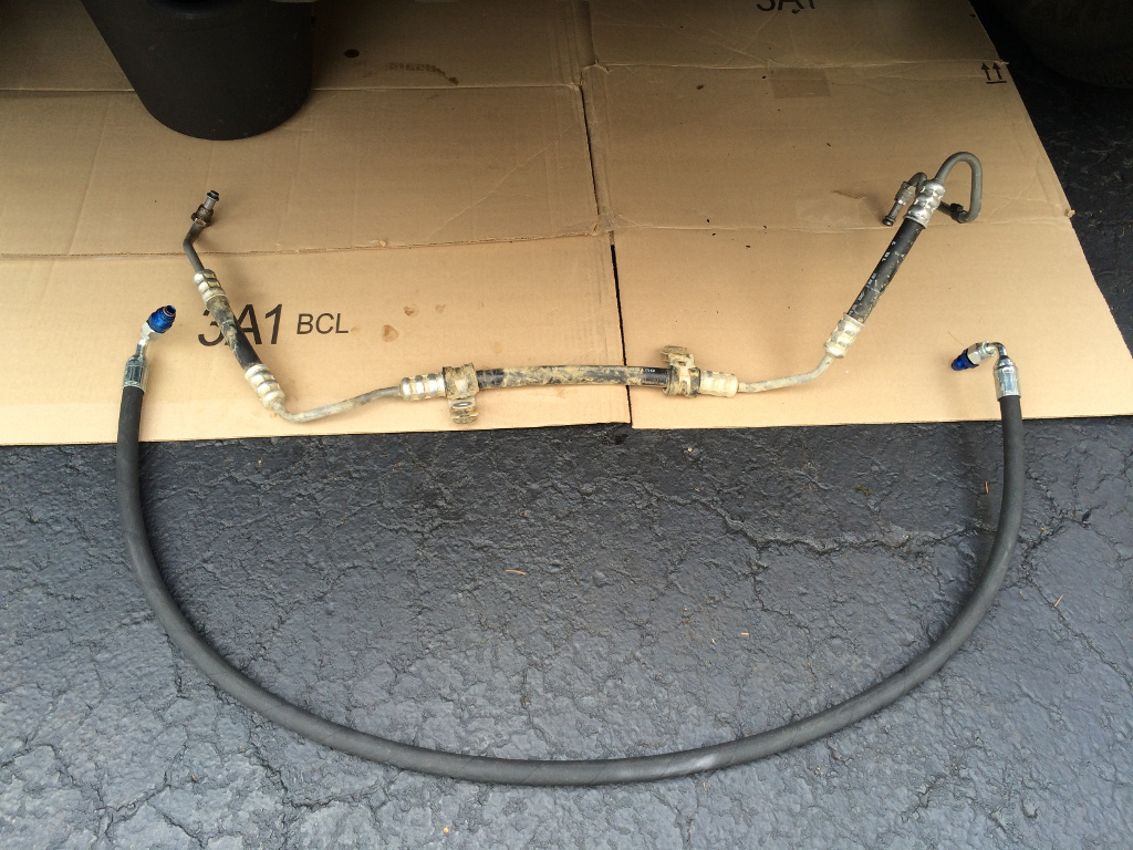
    Stock hose on top, new hose on the bottom. The solid metal portion of the right end of the stock hose is in the way of the charge air pipe that comes up from the intercooler, to the throttle body.

    I succeeded in completing this job without making a mess with power steering fluid! I chose to disconnect the power steering pump side of the hose first (passenger side). First, I used aluminum foil to form a pseudo-funnel to redirect fluid from the bottom of the pump cleanly into a bucket. Once the end of the hose is disconnected, let it drip til it's done.

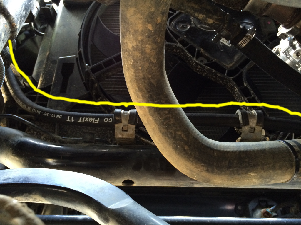
    In the picture above, you can see 2 metal clamps on the original hose. Those are bolted down behind the bottom of the radiator. Once you get the hose out of the engine bay, pry those clamps of and put them on the replacement hose.

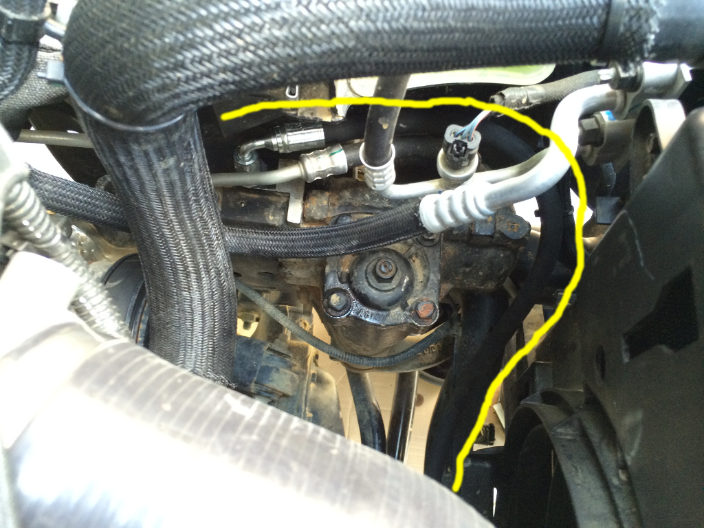
    Here's a view of the new hose connected to the steering gearbox. This is on the driver side, looking down, radiator fan is to the right. This is right where the stock coolant reservoir sits.


    Clamps holding in place behind the radiator:


    And the other end connected to the power steering pump:


    I needed less than a quart of power steering fluid (ATF-4 trans fluid, as specified by owner's manual) to replace what drained out. Instructions tell you a procedure to follow make sure you get air out of the system.

    This is the high pressure side of the system, so it should be quite obvious right away if you have a leak. I had no leaks

    EDIT: I did have a leak. Learn from my mistake: http://jeeplab.com/showthread.php?13...ull=1#post3627
    Last edited by UselessPickles; 11-22-2014 at 01:26 AM.

  6. #6
    UPDATE: new coolant reservoir location: http://jeeplab.com/showthread.php?13...ull=1#post3638


    The second independent/separable step is getting rid of the stock coolant reservoir (it's in the way of the charge air pipe for stage 2 as well), and installing a new reservoir in a different location.

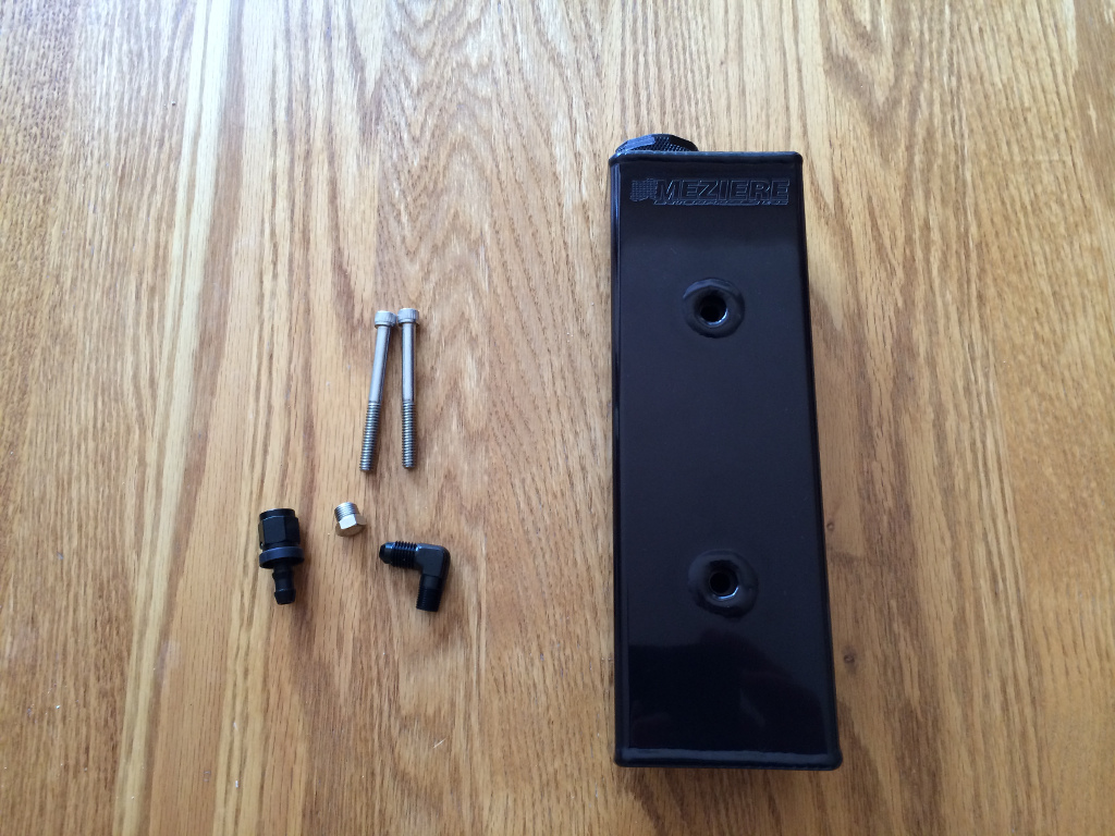
    Here's the new reservoir:


    It's a Meziere 28oz Coolant Recovery Tank: https://www.meziere.com/ps-1444-1377-wr100s.aspx


    And this is where it gets mounted, behind the front bumper on the passenger side:


    This requires drilling holes and tapping threads. Take your time and double check the positioning, mark where you want the holes, etc. I actually mounted mine slightly differently than Prodigy's instructions. Their instructions show the tank mounted slightly further back and lower, causing the bottom of the tank to hang down lower than the part of the frame that it is mounted to. I found that there was barely enough room to mount mine flush with the bottom of the frame. The positioning of the top mounting hole ended up being VERY close to a large existing hole in the frame, so i had very little room for error when drilling that hole.

    Don't repeat my mistake when tapping the threads: I used the drill motor with the thread tap, spun it too fast, and got it stuck in the hole, then ended up snapping the tip off in the hole. That was fun to drill that out. Lesson learned: tap VERY SLOWLY. You're supposed to twist the tap by hand, but I just couldn't keep it steady enough with my hand. I ended up using the drill motor again, but this time I oiled the tap for lubrication, and did my best to simulate twisting by hand with the drill motor by doing short, slow, smooth bursts of drilling, to avoid overheating the tap.

    The original hose from the radiator to the coolant reservoir gets reused. Just run it straight down from the radiator cap and find a path forward to connect up with the new reservoir.


    Yes, you will have to remove the two mounting bolts and pull the reservoir out a bit if you want to take the cap off and check the coolant level in it. I would much prefer another semi-transparent plastic container that is easy to visually check, like the one in the RIPP kit. But the space where RIPP places their reservoir just isn't available with the turbo installed.

    Also, this reservoir is much smaller than the stock reservoir. I spent some time looking up info about how much 50/50 coolant/water mix expands/contracts with temperature. I don't remember specifics, but I did find enough info to conclude that this reservoir is pretty much the smallest you could possibly go for the amount of coolant in the Pentastar. Because it's so close, it might just take a little trial and error to get it filled to the correct level so that it doesn't overflow when hot to the extreme (idling in traffic on a hot summer day), and doesn't allow air to be sucked into the system when cold on the coldest winter days.
    Last edited by UselessPickles; 11-23-2014 at 06:42 PM.

  7. #7
    you will have to remove the two mounting bolts and pull the reservoir out a bit if you want to take the cap off and check the coolant level in it. I would much prefer another semi-transparent plastic container that is easy to visually check, like the one in the RIPP kit.
    You do not need to remove the reservoir to check fluid level. You can just remove the center cover between the grille and the bumper. This will allow access to view fluid level and top off as necessary. Do you have a pic of the Ripp plastic container? i would like to see it...

  8. #8
    Quote Originally Posted by boosted1 View Post
    You do not need to remove the reservoir to check fluid level. You can just remove the center cover between the grille and the bumper.
    I must just have horrible luck with those stupid plastic fasteners that hold the plastic cover down. I usually have to resort to partially or fully destructive methods to remove them. For me, it's quicker/easier to unbolt the reservoir. Have any tips for removing those plastic fasteners?

    Quote Originally Posted by boosted1 View Post
    Do you have a pic of the Ripp plastic container? i would like to see it...
    Here's a couple pics I found online:


    I found the PDF installation guide at one point, but can't find it again now. They have a bracket that mounts using the original bolts on the stock air box support. The reservoir just drops/slides down onto the bracket. It appears to me that they just found an OEM reservoir from some other vehicle that happens to fit in that space, then made a custom bracket for it, but that's just my speculation.

  9. #9
    Thanks jeff for the instructions, i have contaced Dan and he sent me the installation manual but yours better.

    Just finished with installation with couple of issues:

    1- Check engine code P0129 related to map sensor. I have updated the tuner. Might had to clear it and check again but a second issue is there.

    2- A heavy leak between the turbine and the down pipe. (Clamp removed and i can see a space and miss match)

    3- can't figure out the rest of the leak cause the second issue was the big and noisy.

    I am tired now can't think, ill better rest and think later.

  10. #10
    Quote Originally Posted by jeepsking View Post
    A heavy leak between the turbine and the down pipe. (Clamp removed and i can see a space and miss match)
    IMPORTANT: See update at the bottom of this post!

    I found that the connections between the turbine housing, turbo feed pipe, wastegate and downpipe all didn't want to easily match up to each other. I got the best results by doing this:

    1) Loosen all exhaust connections from the turbo back to the head of the engine, including loosening the V-band clamp connecting the the down pipe to the turbine housing, and the 4 bolts holding the turbine to the turbo feed pipe. Loosen the head pipe bolts and ball joints just enough to allow sliding/rotating movement. Loosen everything else more to allow large amounts of movement (especially the 4 bolts holding the turbine to the feed pipe).
    3) Double check that the wastegate is perfectly seated onto the turbo feed pipe, and put the clamp on (squeeze the clamp into place with pliers, but don't tighten yet).
    4) Get the other end of the wastegate firmly seated into the down pipe, and put the clamp on (squeeze the clamp into place with pliers, but don't tighten yet).
    5) Wastegate should be guaranteed to be properly seated and leak-free now.
    6) Mate the turbine housing to the downpipe and partially tighten the v-band clamp. The goal is to have the clamp prevent the joint from separating, but allow it to rotate if necessary. It should be easy get this joint to line up flush because of all the slack in the connection between the turbine housing and the feed pipe. Loosen those 4 bolts more if necessary to get enough slack.
    7) Lightly snug up all 4 bolts (but don't tighten!) holding the turbine housing to the feed pipe. The short flex pipe between the wastegate and downpipe will get flexed/stretched slightly as necessary as these bolts are snugged.
    8) Finish tightening the v-band clamp for the down pipe, and tighten the wastegate clamps.
    9) At this point, the turbo, wastegate and downpipe should be all locked together as one complete assembly, with all joints completely sealed. There should be no other possible orientation of all these interconnected joints.
    10) Loosen the 2 bolts holding the down pipe to the engine. Have someone apply pressure to the turbo to make sure the whole system is shifted as far upward and toward left side of the vehicle as possible as you re-tighten those 2 bolts (reduces contact between the air filter and right-side inner fender liner).
    11) Confirm that the air filter will not be too far forward or rearward, contacting anything (like the trimmed air box support). If necessary, have someone apply pressure forward or rearward on the turbo as you tighten the 4 bolts holding the turbine to the feed pipe.
    12) At this point, the main turbo system should be locked into place where it should be relative to the engine, via the 3 mounting points to the engine. The rest of the exhaust system back to the engine should now just be in whatever orientation is necessary to allow the turbo system to be where it needs to be.
    13) Tighten the pipes to the heads of the engine.
    14) Tighten the ball joints in the exhaust.


    ------------- UPDATE --------------
    Prodigy now has a more detailed and different recommendation for how to install the turbo and pipes. This new method worked better for me. Here's their video:

    ]

    it's important to have another 1-2 pair of hands to help when making the second wastegate connection. I had one person support the weight of the turbo while I laid under the Jeep, reaching up to shift everything around to align the wastegate connection, then another person slilped the clamp over the wastegate connection while I held it in perfect alignment.

    Then when tightening the turbo V-band clamp, do it in stages where you tighten it a bit, then jiggle the connection and tap the clamp with a soft mallet to help get that V-band connection in perfect alignment.
    Last edited by UselessPickles; 12-02-2017 at 11:17 AM.

Posting Permissions

  • You may not post new threads
  • You may not post replies
  • You may not post attachments
  • You may not edit your posts
  •